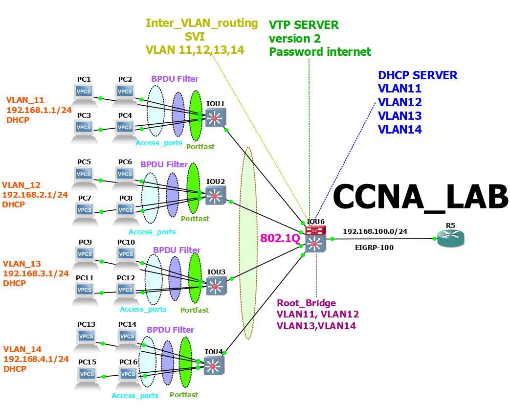
In this lab, we see the configuration of SVI DHCP server VTP Root guard BPDU filter Inter VLAN routing 802.1q and more. This lab is good for CCNA and CCNP students. let's see what we are going to configure.
A Trunk link is a point-to-point link between two network devices. Trunk links carry more than one VLAN. With VLAN trunking, we can extend our configured VLAN across the entire network. Remember, sending information from an access link on one VLAN to another VLAN is not possible without the additional device a router, or an external layer 2 bridge connected between the VLAN. A Trunk link can transport multiple VLAN traffic through a single switch port. A trunk link is not assigned to a specific VLAN in detail...
VLAN Trunking Protocol (VTP) is a Cisco proprietary protocol, as I already said VTP is used to share the VLAN configuration with other switches and maintain consistency throughout that network but information will be passed only if the switch is connected with fast Ethernet or higher ports and also it must be trunk links in detail...
VLAN is a logical grouping of network users and resources connected to administratively defined ports on a switch. VLANs are given the ability to create smaller broadcast domains within layer 2 switched internetworks by assigning different service switches to different subnetworks. A VLAN is treated like its own subnet or broadcast domain, meaning that frames broadcast into the network are only switched between the ports logically grouped within the same VLAN. By default, hosts in a specific VLAN can’t communicate with hosts that are members of another VLAN, so if you want to communicate, we need a router or Inter-VLAN Routing (IVR) in detail...
DHCP (Dynamic Host Configuration Protocol) servers provide all the basic information the client wants to operate on the network, including DNS address, Default Gateway, IP addresses, and subnet. masks and many more in detail...
Spanning tree Portfast is a Cisco proprietary enhanced for spanning trees. Port-fast helps to speed up the network convergence on access ports. Portfast bypasses the listening and learning states 15 + 15 seconds timer and enters the spanning tree forwarding state immediately in detail...
Spanning-tree BPDU Guard is one of the features that help you protect your spanning-tree topology. BPDU Guard prevents loops if another switch is attached to a Portfast port. When BPDU Guard is enabled on an interface, it is put into an error-disable state basically shut down, if a BPDU is received on the interface. It can be enabled in either global configuration mode or interface mode. in detail...
The root guard prevents the wrong switch from becoming the spanning tree root. If a root guard port receives a superior BPDU that might cause it to become a root port, the port is put into a “root-inconsistent” state and does not pass traffic through it. If the port stops receiving these BPDUs, it automatically re-enables itself. in detail...
let's see the configuration:-
Configure the topology as per the diagram
Configure trunk 802.1q
Configure no negotiation and allow only VLAN 11,12,13,14 on the trunk
Configure VTP domain name internetworks password networks
Configure VTP version 2
Configure MLS switch as a Server and rest the switches clients
Configure VLAN_11 VLAN_12 VLAN_13 VLAN_14 on MLS
make sure rest of the switches will get this information
Configure the ports into their VLAN as per the topology
Configure the IP address to VLANs for inter VLAN routing
IP 192.168.1.1/24 to VLAN 11
IP 192.168.2.1/24 to VLAN 12
IP 192.168.3.1/24 to VLAN 13
IP 192.168.4.1/24 to VLAN 14
Configure DHCP server for VLAN 11,12,13,14 on MLS
Make sure all PC in different VLAN get their IP address and other information
Ping from PC-1 to PC in different VLANs
Configure port fast on all the access-ports
Configure MLS switch to become Root bridge for all the VLANs
Configure Root guard on trunk MLS switch
Configure BPDU filter
MSL-SW-(config)#interface range ethernet 1/0-3
MSL-SW-(config-if-range)#switchport trunk encapsulation dot1q
MSL-SW-(config-if-range)#switchport mode trunk
MSL-SW-(config-if-range)#switchport nonegotiate
MSL-SW-(config-if-range)#switchport trunk allowed vlan 11,12,13,14
MSL-SW-(config-if-range)#exit
MSL-SW-#show interface trunk
Port Mode Encapsulation Status Native vlan
Et1/0 on 802.1q trunking 1
Et1/1 on 802.1q trunking 1
Et1/2 on 802.1q trunking 1
Et1/3 on 802.1q trunking 1
Port Vlans allowed on trunk
Et1/0 11-14
Et1/1 11-14
Et1/2 11-14
Et1/3 11-14
Switch-1(config)#interface range ethernet 1/0
Switch-1(config-if-range)#switchport trunk encapsulation dot1q
Switch-1(config-if-range)#switchport mode trunk
Switch-1(config-if-range)#switchport nonegotiate
Switch-1(config-if-range)#switchport trunk allowed vlan 11,12,13,14
Switch-1(config-if-range)#exit
Switch-1(config)#end
Switch-1#show interface trunk
Port Mode Encapsulation Status Native vlan
Et1/0 on 802.1q trunking 1
Port Vlans allowed on trunk
Et1/0 11-14
Switch-2(config)#interface range ethernet 1/1
Switch-2(config-if-range)#switchport trunk encapsulation dot1q
Switch-2(config-if-range)#switchport mode trunk
Switch-2(config-if-range)#switchport nonegotiate
Switch-2(config-if-range)#switchport trunk allowed vlan 11,12,13,14
Switch-2(config-if-range)#exit
Switch-2(config)#end
Switch-2#show interface trunk
Port Mode Encapsulation Status Native vlan
Et1/1 on 802.1q trunking 1
Port Vlans allowed on trunk
Et1/1 11-14
IOU3(config)#interface range ethernet 1/2
IOU3(config-if-range)#switchport trunk encapsulation dot1q
IOU3(config-if-range)#switchport mode trunk
IOU3(config-if-range)#switchport nonegotiate
IOU3(config-if-range)#switchport trunk allowed vlan 11,12,13,14
IOU3(config-if-range)#exit
IOU3(config)#end
IOU3#show interface trunk
Port Mode Encapsulation Status Native vlan
Et1/2 on 802.1q trunking 1
Port Vlans allowed on trunk
Et1/2 11-14
Switch-4(config)#interface range ethernet 1/3
Switch-4(config-if-range)#switchport trunk encapsulation dot1q
Switch-4(config-if-range)#switchport mode trunk
Switch-4(config-if-range)#switchport nonegotiate
Switch-4(config-if-range)#switchport trunk allowed vlan 11,12,13,14
Switch-4(config-if-range)#exit
Switch-4(config)#end
Switch-4#show interface trunk
Port Mode Encapsulation Status Native vlan
Et1/3 on 802.1q trunking 1
Port Vlans allowed on trunk
Et1/3 11-14
MSL-SW-(config)#VTP domain internetworks
Domain name already set to internetworks.
MSL-SW-(config)#VTP password networks
MSL-SW-(config)#VTP mode server
MSL-SW-(config)#VTP version 2
MSL-SW-(config)#end
MSL-SW-#show vtp status
VTP Version capable : 1 to 3
VTP version running : 2
VTP Domain Name : internetworks
VTP Pruning Mode : Disabled
VTP Traps Generation : Disabled
Device ID : aabb.cc00.0600
Switch-1(config)#VTP domain internetworks
Switch-1(config)#VTP password networks
Switch-1(config)#VTP mode client
Switch-1(config)#VTP version 2
Switch-1(config)#end
Switch-2(config)#VTP domain internetworks
Switch-2(config)#VTP password networks
Switch-2(config)#VTP mode client
Switch-2(config)#VTP version 2
Switch-2(config)#end
IOU3(config)#VTP domain internetworks
IOU3(config)#VTP password networks
IOU3(config)#VTP mode client
IOU3(config)#VTP version 2
IOU3(config)#end
Switch-4(config)#VTP domain internetworks
Switch-4(config)#VTP password networks
Switch-4(config)#VTP mode client
Setting device to VTP Client mode for VLANS.
Switch-4(config)#VTP version 2
Switch-4(config)#end
MSL-SW-(config)#VLAN 11
MSL-SW-(config-vlan)#name Go Green Team
MSL-SW-(config-vlan)#exit
MSL-SW-(config)#VLAN 12
MSL-SW-(config-vlan)#name Go Blue Team
MSL-SW-(config-vlan)#exit
MSL-SW-(config)#VLAN 13
MSL-SW-(config-vlan)#name Go Purple
MSL-SW-(config-vlan)#exit
MSL-SW-(config)#VLAN 14
MSL-SW-(config-vlan)#name Go Skey Blue
MSL-SW-(config-vlan)#exit
MSL-SW-#show vlan
VLAN Name Status Ports
---- -------------------------------- --------- -------------------------------
1 default active Et0/0, Et0/1, Et0/2, Et0/3
Et2/0, Et2/1, Et2/2, Et2/3
Et3/0, Et3/1, Et3/2, Et3/3
11 Go Green Team active
12 Go Blue Team active
13 Go Purple active
14 Go Skey Blue active
1002 fddi-default act/unsup
1003 trcrf-default act/unsup
1004 fddinet-default act/unsup
1005 trbrf-default act/unsup
VLAN Type SAID MTU Parent RingNo BridgeNo Stp BrdgMode Trans1 Trans2
---- ----- ---------- ----- ------ ------ -------- ---- -------- ------ ------
Switch-1(config)#interface range ethernet 0/0-3
Switch-1(config-if-range)#switchport mode access
Switch-1(config-if-range)#switchport access vlan 11
Switch-1(config-if-range)#exit
Switch-1(config)#end
Switch-1#
*Oct 1 11:00:36.626: %SYS-5-CONFIG_I: Configured from console by console
Switch-1#
Switch-1#show vlan
VLAN Name Status Ports
---- -------------------------------- --------- -------------------------------
1 default active Et1/1, Et1/2, Et1/3, Et2/0
Et2/1, Et2/2, Et2/3, Et3/0
Et3/1, Et3/2, Et3/3
11 Go Green Team active Et0/0, Et0/1, Et0/2, Et0/3
12 Go Blue Team active
13 Go Purple active
14 Go Skey Blue active
1002 fddi-default act/unsup
1003 trcrf-default act/unsup
1004 fddinet-default act/unsup
1005 trbrf-default act/unsup
VLAN Type SAID MTU Parent RingNo BridgeNo Stp BrdgMode Trans1 Trans2
Switch-2(config)#interface range ethernet 0/0-3
Switch-2(config-if-range)#switchport mode access
Switch-2(config-if-range)#switchport access vlan 12
Switch-2(config-if-range)#exit
Switch-2(config)#end
Switch-2#show vlan
VLAN Name Status Ports
---- -------------------------------- --------- -------------------------------
1 default active Et1/0, Et1/2, Et1/3, Et2/0
Et2/1, Et2/2, Et2/3, Et3/0
Et3/1, Et3/2, Et3/3
11 Go Green Team active
12 Go Blue Team active Et0/0, Et0/1, Et0/2, Et0/3
13 Go Purple active
14 Go Skey Blue active
1002 fddi-default act/unsup
1003 trcrf-default act/unsup
1004 fddinet-default act/unsup
1005 trbrf-default act/unsup
VLAN Type SAID MTU Parent RingNo BridgeNo Stp BrdgMode Trans1 Trans2
Switch-3(config)#interface range ethernet 0/0-3
Switch-3(config-if-range)#switchport mode access
Switch-3(config-if-range)#switchport access vlan 13
Switch-3(config-if-range)#exit
Switch-3(config)#end
Switch-3#show vlan
VLAN Name Status Ports
---- -------------------------------- --------- -------------------------------
1 default active Et1/0, Et1/1, Et1/3, Et2/0
Et2/1, Et2/2, Et2/3, Et3/0
Et3/1, Et3/2, Et3/3
11 Go Green Team active
12 Go Blue Team active
13 Go Purple active Et0/0, Et0/1, Et0/2, Et0/3
14 Go Skey Blue active
1002 fddi-default act/unsup
1003 trcrf-default act/unsup
1004 fddinet-default act/unsup
1005 trbrf-default act/unsup
VLAN Type SAID MTU Parent RingNo BridgeNo Stp BrdgMode Trans1 Trans2
Switch-4(config)#interface range ethernet 0/0-3
Switch-4(config-if-range)#switchport mode access
Switch-4(config-if-range)#switchport access vlan 14
Switch-4(config-if-range)#exit
Switch-4(config)#end
Switch-4#show vlan
VLAN Name Status Ports
---- -------------------------------- --------- -------------------------------
1 default active Et1/0, Et1/1, Et1/2, Et2/0
Et2/1, Et2/2, Et2/3, Et3/0
Et3/1, Et3/2, Et3/3
11 Go Green Team active
12 Go Blue Team active
13 Go Purple active
14 Go Skey Blue active Et0/0, Et0/1, Et0/2, Et0/3
1002 fddi-default act/unsup
1003 trcrf-default act/unsup
1004 fddinet-default act/unsup
1005 trbrf-default act/unsup
VLAN Type SAID MTU Parent RingNo BridgeNo Stp BrdgMode Trans1 Trans2
MSL-SW-(config)#interface vlan 11
MSL-SW-(config-if)#ip address 192.168.1.1 255.255.255.0
MSL-SW-(config-if)#no shutdown
MSL-SW-(config-if)#exit
MSL-SW-(config)#
MSL-SW-(config)#interface vlan 12
MSL-SW-(config-if)#ip address 192.168.2.1 255.255.255.0
MSL-SW-(config-if)#no shutdown
MSL-SW-(config-if)#exit
MSL-SW-(config)#
MSL-SW-(config)#interface vlan 13
MSL-SW-(config-if)#ip address 192.168.3.1 255.255.255.0
MSL-SW-(config-if)#no shutdown
MSL-SW-(config-if)#exit
MSL-SW-(config)#
MSL-SW-(config)#interface vlan 14
MSL-SW-(config-if)#ip address 192.168.4.1 255.255.255.0
MSL-SW-(config-if)#no shutdown
MSL-SW-(config-if)#exit
MSL-SW-#show ip interface brief
Interface IP-Address OK? Method Status Protocol
Vlan11 192.168.1.1 YES manual up up
Vlan12 192.168.2.1 YES manual up up
Vlan13 192.168.3.1 YES manual up up
Vlan14 192.168.4.1 YES manual up up
MSL-SW-(config)#service dhcp
MSL-SW-(config)#ip dhcp pool vlan11
MSL-SW-(dhcp-config)#network 192.168.1.2 255.255.255.0
MSL-SW-(dhcp-config)#default-router 192.168.1.1
MSL-SW-(dhcp-config)#dns-server 8.8.8.8
MSL-SW-(dhcp-config)#exit
MSL-SW-(config)#service dhcp
MSL-SW-(config)#ip dhcp pool vlan12
MSL-SW-(dhcp-config)#network 192.168.2.2 255.255.255.0
MSL-SW-(dhcp-config)#default-router 192.168.2.1
MSL-SW-(dhcp-config)#dns-server 8.8.8.8
MSL-SW-(dhcp-config)#exit
MSL-SW-(config)#service dhcp
MSL-SW-(config)#ip dhcp pool vlan13
MSL-SW-(dhcp-config)#network 192.168.3.2 255.255.255.0
MSL-SW-(dhcp-config)#default-router 192.168.3.1
MSL-SW-(dhcp-config)#dns-server 8.8.8.8
MSL-SW-(dhcp-config)#exit
MSL-SW-(config)#service dhcp
MSL-SW-(config)#ip dhcp pool vlan14
MSL-SW-(dhcp-config)#network 192.168.4.2 255.255.255.0
MSL-SW-(dhcp-config)#default-router 192.168.4.1
MSL-SW-(dhcp-config)#dns-server 8.8.8.8
MSL-SW-(dhcp-config)#exit
MSL-SW-#show ip dhcp binding
Bindings from all pools not associated with VRF:
IP address Client-ID/ Lease expiration Type State Interface
Hardware address/
User name
192.168.1.2 0100.5079.6668.00 Oct 02 2024 11:07 AM Automatic Active Vlan11
192.168.1.3 0100.5079.6668.01 Oct 02 2024 11:07 AM Automatic Active Vlan11
192.168.2.2 0100.5079.6668.04 Oct 02 2024 11:07 AM Automatic Active Vlan12
192.168.2.3 0100.5079.6668.05 Oct 02 2024 11:08 AM Automatic Active Vlan12
192.168.3.2 0100.5079.6668.08 Oct 02 2024 11:08 AM Automatic Active Vlan13
192.168.3.3 0100.5079.6668.09 Oct 02 2024 11:08 AM Automatic Active Vlan13
192.168.4.3 0100.5079.6668.0d Oct 02 2024 11:08 AM Automatic Active Vlan14
MSL-SW-(config)#ip routing
PC1> ip dhcp
DDORA IP 192.168.1.2/24 GW 192.168.1.1
PC1> ping 192.168.1.3
84 bytes from 192.168.1.3 icmp_seq=1 ttl=64 time=5.950 ms
84 bytes from 192.168.1.3 icmp_seq=2 ttl=64 time=1.285 ms
84 bytes from 192.168.1.3 icmp_seq=3 ttl=64 time=2.572 ms
84 bytes from 192.168.1.3 icmp_seq=4 ttl=64 time=2.253 ms
84 bytes from 192.168.1.3 icmp_seq=5 ttl=64 time=1.654 ms
PC1> ping 192.168.2.2
84 bytes from 192.168.2.2 icmp_seq=1 ttl=63 time=18.753 ms
84 bytes from 192.168.2.2 icmp_seq=2 ttl=63 time=5.606 ms
84 bytes from 192.168.2.2 icmp_seq=3 ttl=63 time=6.312 ms
84 bytes from 192.168.2.2 icmp_seq=4 ttl=63 time=5.498 ms
84 bytes from 192.168.2.2 icmp_seq=5 ttl=63 time=3.911 ms
PC1> ping 192.168.3.2
84 bytes from 192.168.3.2 icmp_seq=1 ttl=63 time=17.571 ms
84 bytes from 192.168.3.2 icmp_seq=2 ttl=63 time=5.690 ms
84 bytes from 192.168.3.2 icmp_seq=3 ttl=63 time=7.361 ms
84 bytes from 192.168.3.2 icmp_seq=4 ttl=63 time=4.170 ms
84 bytes from 192.168.3.2 icmp_seq=5 ttl=63 time=4.948 ms
PC1> ping 192.168.4.2
84 bytes from 192.168.4.2 icmp_seq=1 ttl=63 time=18.701 ms
84 bytes from 192.168.4.2 icmp_seq=2 ttl=63 time=5.275 ms
84 bytes from 192.168.4.2 icmp_seq=3 ttl=63 time=3.818 ms
84 bytes from 192.168.4.2 icmp_seq=4 ttl=63 time=5.806 ms
84 bytes from 192.168.4.2 icmp_seq=5 ttl=63 time=6.827 ms
Switch-1(config)#interface range ethernet 0/0-3
Switch-1(config-if-range)#spanning-tree portfast
Switch-1(config-if-range)#end
%Warning: portfast should only be enabled on ports connected to a single
host. Connecting hubs, concentrators, switches, bridges, etc... to this
interface when portfast is enabled, can cause temporary bridging loops.
Use with CAUTION
%Portfast will be configured in 4 interfaces due to the range command
but will only have effect when the interfaces are in a non-trunking mode.
Switch-2(config)#interface range ethernet 0/0-3
Switch-2(config-if-range)#spanning-tree portfast
%Warning: portfast should only be enabled on ports connected to a single
host. Connecting hubs, concentrators, switches, bridges, etc... to this
interface when portfast is enabled, can cause temporary bridging loops.
Use with CAUTION
%Portfast will be configured in 4 interfaces due to the range command
but will only have effect when the interfaces are in a non-trunking mode.
Switch-2(config-if-range)#exit
Switch-3(config)#interface range ethernet 0/0-3
Switch-3(config-if-range)#spanning-tree portfast
%Warning: portfast should only be enabled on ports connected to a single
host. Connecting hubs, concentrators, switches, bridges, etc... to this
interface when portfast is enabled, can cause temporary bridging loops.
Use with CAUTION
%Portfast will be configured in 4 interfaces due to the range command
but will only have effect when the interfaces are in a non-trunking mode.
Switch-3(config-if-range)#exit
Switch-4(config)#interface range ethernet 0/0-3
Switch-4(config-if-range)#spanning-tree portfast
%Warning: portfast should only be enabled on ports connected to a single
host. Connecting hubs, concentrators, switches, bridges, etc... to this
interface when portfast is enabled, can cause temporary bridging loops.
Use with CAUTION
%Portfast will be configured in 4 interfaces due to the range command
but will only have effect when the interfaces are in a non-trunking mode.
Switch-4(config-if-range)#exit
MSL-SW-(config)#spanning-tree vlan 11,12,13,14 root primary
MSL-SW-(config)#end
MSL-SW-#show spanning-tree
VLAN0001
Spanning tree enabled protocol ieee
Root ID Priority 32769
Address aabb.cc00.0600
This bridge is the root
Hello Time 2 sec Max Age 20 sec Forward Delay 15 sec
MSL-SW-(config)#interface range ethernet 1/0-3
MSL-SW-(config-if-range)#spanning-tree guard root
MSL-SW-(config-if-range)#end
*Oct 2 17:26:10.692: %SPANTREE-2-ROOTGUARD_CONFIG_CHANGE: Root guard enabled on port Ethernet1/0.
*Oct 2 17:26:10.693: %SPANTREE-2-ROOTGUARD_CONFIG_CHANGE: Root guard enabled on port Ethernet1/1.
*Oct 2 17:26:10.693: %SPANTREE-2-ROOTGUARD_CONFIG_CHANGE: Root guard enabled on port Ethernet1/2.
*Oct 2 17:26:10.693: %SPANTREE-2-ROOTGUARD_CONFIG_CHANGE: Root guard enabled on port Ethernet1/3.

